The interesting, the weird and the technical world of Nuclear Medicine, geared towards students. It's a blog for students who are in their clinical practicum .... or for those who are just curious.
This is an interesting case in that it involved a patient to be injected with two different renal imaging agents: DTPA and DMSA. The radiation oncologists wanted to asses the renal function within this patient, prior to having radiation therapy for endometrial cancer. The big problem was that the patient has a left pelvic kidney, and they feared that it would be ablated during the treatment. The CT image below details where the kidney lies within the pelvis.
Fig. 1 Sagittal slice of the patient. Note the ovoid shaped organ on the bottom right of the image just below the sacrum.
The assessment of renal function in our department generally includes the determination of glomerular filtration rate (GFR) and the split renal function (differential renal function) to help the clinicians determine the implications of residual kidney function if a kidney or kidneys are irradiated. It is also used to determine whether a person is a good candidate for kidney donation, since our hospital is a major organ transplant centre. The assessment of renal function is a routine procedure for us.
We perform our renal scans mainly with DTPA, along with corresponding blood samples at time 0 pre-injection, 1 hour post injection and at 3 hours post injection. We combine this with the Gates analysis method to get an idea of the overall kidney function. The images below are what we have obtained using the DTPA and blood sampling method. All dynamic and static images with respect to the kidneys are performed in the supine position.
Fig. 2 Both camera and blood sampling methods are used to determine the GFR. Regions of interest (ROI's) are drawn over the kidneys, bladder and aorta as per protocol. Associated background regions are drawn corresponding to each kidney.
Fig. 3 Split renal function (differential) is primarily determined by the camera method.
Fig. 4 The renal dynamic and static images are made into reports to assess drainage from the kidneys as well as to determine the quality of the injection (ie. an interstitial injection?). However if you look carefully on the top row of images the left pelvic kidney, over time, becomes obscured by the bladder.
We perform continuous imaging over a 20 minute period and then static views of pre and post void kidneys (standing), along with the injection site to assess for residual activity.
In this case here, as you can see from the images above, the assessment of the right kidney seems to be straight forward, but the problem is the assessment of the left pelvic kidney. In Fig. 3, over time, it becomes obscured by the bladder.
(Note, I have tried to load the dynamic acquisition to demonstrate this more clearly, but could not get the correct intensity to illustrate this event)
The problem is, our reporting radiologist could not be confident in reporting the GFR values nor the split renal function, since the regions of interest (ROI's) would incorporate the expanding bladder and would result in an inaccurate estimation of these values.
Essentially our reporting radiologist spoke with the requesting radiation oncologists to consult them with regards to the imaging. To make a long story short, in the end, the GFR values were not as important as the split renal function. Thus to avoid the bladder uptake, DMSA was used to scan the kidneys again and a geometric mean was used to determine the split renal function. Below are the images of the DMSA scan.
Fig. 5 Anterior and posterior images of the kidneys were obtained using DMSA. A geometric mean was used to better estimate the split renal function. Imaging was performed in the supine position.
The use of the DMSA essentially limited the amount of bladder activity seen, but provided good parenchymal imaging to allow for the split renal function to be calculated.
Takayasu arteritis is one of the indications that we perform an F18 FDG PET/CT scan on, primarily as a research protocol. This is one of those research studies that we do not do very frequently but once in awhile they pop up on our list. What is interesting about this condition, besides the name, is that this is a rare condition that causes vasculitis in the large vessels, such as the aorta and it's branches. The history of Takayasu arteritis is pretty interesting as well. Originally this vascular disease was reported by Dr. Mikito Takayasu, an ophthalmologist in 1908 at the 12th Annual Meeting of the Japan Opthalmology Society. It basically came about with the appearance of "coronary anastomosis" in the eyegrounds and arteriovenous anastomosis around the papila of a 21 year old woman that Dr. Takayasu was examining. Further investigation lead others to report "pulselessness" in their patients which is another clinical feature. The radial, brachial and carotid pulses are absent in these patients as the result of the ischemic cerebrovascular circulation. There's more, but if you click on the link at the start of this paragraph, you can read the rest. So here is what it looks like in PET:
Fig. 1 FDG PET imaging of a patient with Takayasu arteritis. Abnormal increased activity are identified along the brachiocephalic and proximal right and left common carotid arteries.
Fig. 2 A fused image denoting the areas of uptake with anatomical features.
Fig. 3 Sagittal fused image with uptake through the common carotid artery.
The preparation for the Takayasu arteritis scans are fairly similar to the other oncological preps that we do in the department except for the fact that we scan with the arms down, we wait for a 90 minute uptake (since the appearance of the inflamed arteries are very subtle thus maximizing the uptake time is essential) and we use an ideal body weight (IBW) calculation. The cut off glucose measurement is around 11.0mmol/l. This is slightly higher than the normal cut off of 9.8mmol/l for the rest of our scans. Imaging is taken from the base of the skull to mid thigh, but 4 minutes per bed for the PET as oppose to the 3 minutes per bed with most of our oncological studies.
As you can see in Fig. 1, there is abnormal increased activity identified along the brachiocephalic and proximal right and left common carotid arteries. There is also increased activity in the descending aorta at the L2-L3 vertebra, which I did not capture on my screen shots. PET/CT would probably not be the first choice in terms of imaging with a suspected case of Takayasu arteritis, the more likely options would be CT angiography or MRI to examine the nature of the large vessels.
I always get mixed up when it comes to sarcoids and sclerodermas when written on a requisition. Currently we perform imaging on these patients to help the clinicians to determine the extent of their patient's disease, but I still get confused as to the nature of the disease and their processes. So this portion of the blog is partly to help me and anyone out there that are in the same position. I have tried to put this into a chart format, but it doesn't translate well into the blog.
Sarcoid: This is an inflammatory disease that can potentially affect multiple organs within the body. It most often starts within the lungs or lymph nodes, but it does not limit it self to these areas. The inflammation (sarcoidosis) is not necessarily caused by an autoimmune response, since this is not an autoimmune disease, but the cause of this inflammation is uncertain. The most distinguishing feature about sarcoids is that they deposit granulomas (microscopic lumps of inflammation). They sometimes clear up on their own or they can become fibrotic if they remain in the body if they do not heal. The most famous entertainer to die from sarcoidosis was Bernie Mac. His condition was primarily localized to his lungs, but sarcoids, like I mentioned before can affect any organ. Here at our facility we image and follow these patients when they become part of the CADRE study. CADRE represents the Cardiac FDG-PET Registry Study. As part of the cardiac program, we look at the extent of their disease via a whole body PET/CT, which we append to their Tc-99m myocardial perfusion studies. Along with the whole body PET/CT, we will perform a quick FDG viability study of their heart while in the department. Most of these patients have their cardiac workup prior to coming to PET. Approximately 25% of all sarcoids involve the heart, and about 13-25% of all sarcoids deaths are related to cardiac insufficiencies such as heart failure, ventricular tachyarythmia or conduction disturbances.
Fig. 1 Extensive uptake of FDG within the thorax, liver, spleen and both kidneys, correlating with the patients known sarcoidosis.
We also perform gallium-67 whole body imaging to localize the areas of inflammation, in particular the lungs. But quite honestly, we do not perform these routinely, and having said that, I don't think I have ever seen one that was positive. UPDATE January 2, 2012: I will take back that last comment about not seeing a positive gallium scan for sarcoidosis. The image below was taken 48 hours post Ga-67 injection. A whole body gallium scan was performed and there was uptake within the lungs consistent with sarcoidosis.
Fig. 2 Uptake in the hilum and the lungs, consistent with sarcoidosis
Scleroderma: This is the result of inflammation in connective tissue featuring the formation of scar tissue (fibrosis) in the skin and organs of the body. Scleroderma is an autoimmune disease, as the result of an overactive immune system. They have specific antibody markers such as ANA, anticentromere or antitopoismerase in their blood stream which suggests autoimmunity.
We perform gallium imaging for scleroderma, but rarely. I have not come across this condition with regards to the patient's history for PET/CT imaging.... yet. I do not have any images to show from our facility and there isn't much on the web either.
Fig 1 WBI scan performed 10 days post 125mCi treatment of I-131 therapy for thyroid Ca.
A whole body iodine scan was performed 10 days post I-131 therapy for a patient who was diagnosed with thyroid cancer. For the most part the scan seems relatively normal, with residual activity within the thyroid bed and salivary glands. The liver is within normal limits. However in the lower left hemipelvis, there appears to be an increased I-131 avidity. Of course to investigate this further we performed a SPECT/CT.
Above is the MIP for the SPECT (doesn't look like much), but when fused with the CT, the following is presented.
Fig. 2 Sagittal section of the I-131 activity. The fat containing mass measures approximately
5.8 x 3.3 cm.
Fig. 3 Coronal section, noting the uptake in the lower left hemipelvis.
The I-131 fat containing lesion within the left pelvis is in keeping with a left ovarian teratoma. These are also know as an ovarian dermoids. Most dermoids/teratomas are benign, and they contain a mix bag of mature and immature tissue such as skin, hair, thyroid tissue, sweat glands, blood, cartilage and even teeth! Generally the appearance of fat within the teratoma along with an irregular component of coarse calcifications help to distinguish these entities when imaging with CT and MRI. The gross anatomy is quite interesting to look at, since they are varied in nature with respect to their appearance and construction.
Needless to say this patient presented to our department with late stage melanoma. A new lung nodule had presented itself on the right lung from a chest x-ray and a PET/CT study was ordered and performed according to departmental protocol.
The patient has had extensive surgery to remove the melanoma from the lower back, along with excision of lymph nodes. The patient also had a previous bout Bowen's disease over the right breast with further metastasis to the left axillary nodes. Upon follow up with the medical oncologist, post surgery, a chest x-ray was performed and it noted a right solitary lung nodule.
The PET/CT was performed and the following images demonstrate extensive and diffuse metabolically active metastatic adenopathy, as well as skeletal, pulmonary, liver, splenic and small bowel metastases.
Fig. 1 Multiple foci of metabolic activity of F18-FDG
Fig. 2 Sagittal fused image of the patient, noting multiple F18 FDG uptake in the spine
At our facility for indications of single pulmonary nodule (SPN) or for non small cell carcinoma (NSCLC) we normally scan from the top of the head to mid thigh. If they have had a previous MRI of the head to determine brain metastases, then we will scan from the base of the skull to mid thigh. However in this case, the patient has had a previous history of melanoma, we decided to scan from the top of the head to their feet. This is our normal protocol with regards to melanoma patients. Basically we performed our melanoma protocol on the patient referred for a lung indication. Generally it takes about 30-35 minutes to scan from the top of the head to their feet depending on the height of the patient. Considering that our PET/CT is an old Seimens Biograph with a 2 slice CT, it does take up a bit of time with respect to the CT acquisition. In addition to this, we do not have the the time of flight (ToF) capabilities to decrease our acquisition times of our PET. However, we are replacing our Biograph with a new machine, since the 2 slice Biograph has come to the end of life for servicing. Anyone interested in a PET/CT unit for training or for a back up?
Fig. 1 Whole body iodine, 10 days post administration of a therapeutic dose of I-131.
Whole body iodine (WBI) imaging was performed on a patient who was administered 3.7GBq of I-131 ten days prior for papillary carcinoma. A total thyroidectomy was also performed as part of the treatment process earlier in the year.
For the most part the thyroid bed was unremarkable as well as the rest of the image, except for a focal uptake in the right upper quadrant. Generally the technologists are fairly cautious at our facility, since a metastatic survey was being performed, a SPECT/CT of the area was also included in the study.
Fig. 2 Coronal section of the SPECT/CT, noting the uptake within the liver. Most likely being gallbladder uptake of the I-131.
Fig. 3 Transaxial CT used in conjuction with the SPECT to localise the I-131 uptake.
Fig. 4 Fused transaxial SPECT/CT, confirming the uptake of the radioactive iodine is inside the gallbladder.
Why is this interesting? Well for one thing, this is something that we do not normally see on our WBI images. Normally we see diffuse liver uptake in this area, but it is not totally uncommon to visualise the gallbladder. This is well documented in the literature and the article does discuss some possibilities of what can potentially cause this normal uptake. Conditions such as cholecystitis, hypokinetic gallbladder function due to stones or an abnormal gallbladder morphology are just some of the potential reasons. Most often an ultrasound is ordered to confirm or correlate if there are any underlying issues that may be involved with the gallbladder.
Bottomline, gallbladder uptake is normal. It is not commonly seen, but from a technical perspective we would rather be "safe than sorry" by performing extra imaging such as a SPECT/CT. Iodine is not the best isotopes to image with and with high energy collimators, it would have been tough to identify based on static images.
Our first patient, who has a long standing history of hepatocellular carcinoma (HCC), was excluded as a surgical candidate to remove the tumour in the right lobe of the liver because the patient suffers from portal hypertension and low platelets. The alternative consideration was for transcatheter arterial chemoembolization (TACE) to treat the tumour, however somehow this patient ended up in the trial study of Yittrium-90 Theraspheres at our facility (click on link for further reading)
A mesenteric angiography and embolization was performed as the first step of the selective internal radiation therapy. The reasoning is to ensure the blood flow localizes into the tumour site while sparing normal healthy sites when the Y-90 is delivered. The mircocatheters where inserted through the right femoral artery and threaded to the right hepatic and left hepatic arteries for the arteriography. The right gastric artery, which arose from proximal left hepatic artery, was embolized with vortex coils. Furthermore the gastroduodenal artery was emoblized as well, leaving patent the common hepatic artery, the left and right hepatic arteries.
Fig. 1 Infusion of contrast through the right hepatic artery. Note the embolization coils below.
Fig. 2 Infusion of contrast through the right hepatic artery, outlining the tumour in the right lobe.
Fig. 3 The right lobe tumour is now fully visualized, with limited shunting. However there is still extraneous vascularity. Thus the lung shut fraction is calculated to quantitate the amount.
After the embolization process, Tc-99m MAA was injected through the microcatheter for the lung shunt study. After the injection, the patient was stabilzed for transport to Nuclear Medicine, and the following images were taken.
Fig. 4 Anterior and posterior images were taken to determine any major shunting of blood to the lungs or stomach.
Fig. 5 Regions of interest were drawn over the lungs and liver and a geometric mean was calculated to determine the lung shunt fraction (LSF).
Lung shunt fraction was calculated to be 3.0%. There is no cut off with regards to the LSF value to be excluded from the treatment. However it is the discretion of the interventional radiologist who will be administering the Y-90 to determine the patient's inclusion within the treatment study.
Two weeks after the initial angiography and embolization, the Y-90 theraspheres were adminstered. Based on the size and volume of the tumour which the interventional radiologist calculated prior to the administration, we wanted to give approximately 2.5Gbq of Y-90 to deliver 120Gy to the tumour site. Nordion which supplies the theraspheres, has an excel worksheet to help with the ordering of the Y-90 dose to ensure the proper calibration of the actual dose. In the end, the amount that we calculated (approximation) of the dose delivered to the tumour site was about 2.49GBq, based on a 1.7% residual activity remaining in the Y-90 administration vial. Overall the tumour received 120.7Gy with the lungs receiving approximately 3.73Gy, based on the LSF value.
Having worked through our first patient it is important to address the fact that most Nuclear Medicine technologists are accustomed to working with radioactive materials. However the interventional radiology (IR) technologists and some IR doctors do not. The dose rate is quite high with respect to the Y-90 vial.... but we normally do not tell them how high it really is. Thus it is a good idea that you get them on board with respect to working with radioactive materials and how to handle these materials without causing too much of a mess. The reason why, is that they are most likely going to set up the Y-90 administration set, since they have much more experience than Nuclear Medicine technologists in a sterile field. Plus it will be the IR doctors (at least at our site), that will be injecting the Y-90.
Fig. 6 An unassembled administration set. Everything is performed in a sterile field. I will endeavour to update this image, once everything is connected together, when our next patient arrives. Which should be in 2 weeks time.
Sorry about not posting anything since May. The "kids" are now coming back to clinical training at the hospital and there will undoubtedly be lot's to post.
Stay tuned. Will report on our first Therasphere patient coming on September 11. It will be interesting.
Performing EC20 patients at the moment. Will be having a look at that as well and explaining what we are doing.
Fig. 1 Patient presents with multiple rib fractures as well as a fracture of the sternum
So what's wrong with this picture? There are several things as you can note with multiple rib fractures and a sternal fracture as well. Originally the patient was to have scans on the hands and wrist as indicated on the requisition. A total body scan was performed with locals of the hands and wrist. The locals were unremarkable, but the chest and ribs are very remarkable.
Some clues for you. No recent thoracic surgery or recent motor vehicle accident. The patient walked into the department with no deficits. However, and this might give it away, he did recently have a heart attack.
If you have guessed it, this person was a recipient of CPR administration a month earlier after he had a heart attack. The delivery of chest compressions from the CPR contributed to the current presentation. If this was me, forget the CPR, just use the AED's and zap away!
Click here for another example that I found online in regards to bone scans and CPR.
Just got back from Chicago... (fun town), on a training seminar in regards to TheraSpheres. For those in the United States and Europe, this might be routine practise in treating liver cancers (hepatocellular carcinoma HCC), but not so much here in Canada. There are only a few places in Canada that are performing these procedures (BC, Alberta) but not sure what type of volumes they have in regards to this type of treatment. The Nordion sales reps have stated that they have some type of involvement within these regions.
At any rate what is a TheraSphere? They are glass beads with Yittrium-90 attached to the surface. The beads themselves are biocompatible and insoluble and have a mean size between 20 - 30um. These beads are injected through a femoral line while undergoing a hepatic angiogram in Interventional Radiology (IR) and the beads are deposited close to the site of the liver lesion that you want to treat.
What's tricky about this is, figuring out the blood supply to the region of the liver in and around the tumour site(s). For the most part the blood flow to the liver is fairly predictable, but with respect to some patients it's a bit more complicated because of a variety of arterial variants, parasitization of flow, accessory arteries, retrograde blood flow etc. that if not found with a thorough investigation, the deposition of the TheraSpheres will not go entirely to the tumour, but elsewhere within the body. This is not a good thing, since adverse reactions may potentially occur. The case studies illustrated these quite well at the training seminar. However, for the most part Yittrium-90 radioembolization of the HCC tumours has several advantages in that it has a lower toxicity profile in comparison to transarterial chemoembolization.
So what does TheraSpheres have to do with Nuclear Medicine? Well for the most part we assay and deliver the Yittrium-90 to the angiography suite, and from there the IR techs and the IR doctors take care of the rest with respect to the injection and the clean up. This will vary from site to site, depending upon the level of comfort and training in dealing with radioactive materials.
However even before this occurs, Nuclear Medicine is important in determining extra hepatic shunting to the lungs or gastrointestinal tract as part of the selection process in figuring out who are good candidates for this treatment.
150MBq of Tc-99m MAA is injected with a microcatheter into the hepatic artery after coil embolization of all visible non hepatic arterial flow. Basically, whatever blood flow that doesn't deal with the liver, they get clamped down with coils, in order to figure extrahepatic flow. The image below is an example of this type of imaging.
Fig. 1 ROI's drawn over the lungs and liver to determine the counts for geometric calculations to determine the Lung Shunt Function (LSF)
Anterior and posterior images are taken to determine regions of interest (ROI) to find out the Lung Shunt Fraction (LSF). The geometric means are calculated from the lungs and liver using the numbers from the ROI's and are used in this equation:
LSF = Lungs / (Liver + Lungs) *100
The reason why this is important is because it helps in determining the dosimetry calculations for pre and post treatment. This is important since you need to know how much radiation to give given a specific volume of liver that you plan to treat without affecting other parts of the body (ie. lungs).
There is the question of planar versus SPECT/CT imaging with MAA. At the training seminar, planar imaging was described, but others have suggested performing SPECT/CT. Since at our site we have limited experience with this protocol, we would need to speak to the IR doctors and the Nuc Med doctors to figure out what they want.
- 37 -185 MBq Tc-99m MAA, injected in IR and the patient delivered to Nuclear Medicine
Equipment:
- Any large FOV dual detector gamma camera, with LEAP or LEHR collimation
Imaging:
Option 1: The patient is positioned supine under the gamma camera and 4 images are acquired. Anterior and posterior images of the abdomen and of the thorax are acquired separately
Option 2: The patient is positioned supine under the gamma camera and a whole body scan is acquired
Camera Parameters:
- Acquisition matrix = 256 X 256
- Zoom = 1.45 or less to ensure all activity visible in FOV; total counts >1M
- Counting time - 5mins per 74 MBq administration of Tc-99m
- Dual headed gamma camera, with SPECT/CT capability
Imaging:
- 30 minutes post injection of Tc-99m MAA, anterior and posterior planar images of the whole body
- SPECT/CT afterwards
Camera Parameters:
- SPECT - 128 X 128 matrix
- 128 frames (25 secs/frame)
- CT - 130 keV, 17 mAs, 5mm slices
There is also talk about PET/CT imaging as well. Since Yittrium-90 is a beta emitter, having the patient come back the following day after treatment allows imaging of the distribution and deposition of the microspheres within the body.
Anyway, there is a lot to know about this procedure and I am only scratching the surface. At our facility we have had some experience with this many years ago, but now there is a real push with some of the doctors at the hospital to revisit this type of treatment again.
Stay tuned........
Update: Check out Theraspheres Part Deux, in this blog site. We've performed out first LSF and treatment.
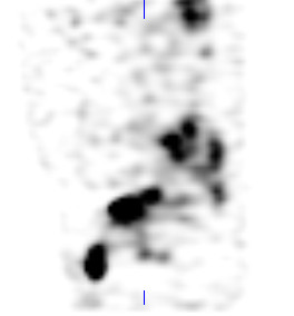
Fig. 1 Post 72 hour whole body gallium imaging for a 74 year old patient, with B cell lymphoma
Gallium scans, in general, are fairly routine in helping clinicians to understand the extent of certain lymphomas in their patients. For the most part PET imaging is the standard of care in many parts of the world, but with limited access to this type of imaging in certain provinces, we still rely on gallium (ole faithful).
What is interesting about the image above is the location of the gallium avid tumours. I personally have never seen uptake in the actual arm itself. The images above describes the uptake in the right infraclavicular lymph nodes, right axillary lymph nodes, soft tissues lateral to the mid shaft of the humerus and soft tissues posterior/lateral to the distal shaft of the humerus. A SPECT/CT was performed, which included the arms and thorax. The sagittal slice reconstruction below helps in clarifying the location of the tumours in the arm.
Fig. 3 Sagittal reconstruction of the right arm localizing the gallium avid tumours. The video below is the 2-bed SPECT scan of the patient.
The patient initially presented with anemia. Upper and lower gastrointestinal investigations did not reveal anything out of the ordinary, but the blood work for hemoglobin, mean corpuscular volume (MCV) and ferritin results were abnormal. The lumps and nodules in the right arm have been present for 8 years, and it was only recently that they began to grow in size, but were not painful. The patient was diagnosed with diffuse B cell lymphoma and is currently undergoing treatment.
Sorry about the appearance of the image... I was not able to invert the colour scheme.
However, this patient presented to our department to determine if osteomyelitis was present in her right upper jaw. In short, our doctors were unable to decide if the site had osteomyelitis, because of other confounding circumstances such as the patient's recent dental work in the same area. It was tough because they were unsure if there was some type of odontogenic infection occurring as well. Plus the extent of the underlying bone that was involved in this infection was difficult to resolve given the patient's underlying bony lesions. The sulphur colloid (bone marrow images) and the delayed In-111 WBC images are not included for viewing because the interesting point about this case, is the actual total body bone scan itself.
McCune Albright Syndrome (polyostotic fibrous dysplasia) is a genetic disorder that affects the bones and pigmentation of the skin. It is not a common disorder and the exact number of cases in the United States and internationally is not known. However what is interesting are the multiple abnormal foci of increased activity noted within the bones, this in keeping with the nature of the syndrome. Anyway I thought this was more interesting than the osteomyelitis component of this case.
Fig. 1 Total body bone scan of a patient diagnosed with renal cell carcinoma.
As a technologist what would you do after the total body bone scan (TBBS) was complete? I think one of our main duties are to review the images to see if there are any asymmetrical bone uptake relating to the patient's history and to take extra pictures if needed. With respect to the images above, there are a few spots, in particular the spine, but other than that nothing too remarkable to talk about. Unless you take a closer look at the pelvis. Is this contamination or is this "something else"? Well it has to be something else or else it wouldn't be on this blog.
So, what are our options to figure out, what's going on in the pelvis?
a. Take a quick lateral view, to see if this is truly contamination
b. SPECT or SPECT/CT
c. Squat view on the camera (ie. have the patient sit on the camera) to separate bone versus soft tissue
Since we have a hybrid system, we SPECT/CT'ed the pelvis. So the question you are asking yourself right now is, why did we opt to do this? Well if you look at urine contamination on patients in general, it usually looks more "drawn out" - dribbling with smaller spots. Also in this TBBS the margins of the "spot" below the bladder proper, are smooth and well defined... so it doesn't really fit with our pre notion of what contamination would look like. Plus, we had the time and we needed the "billings" and the workload units, so we did it... I am joking of course (as someone pointed out) .... And this is what we got:
The SPECT is interesting. The "spot" is anterior to the bladder, but really not on the surface of the skin. Below is the CT transaxial slice of the pelvis from the SPECT/CT.
Fig. 2 Transaxial CT image of the pelvis from the SPECT/CT scan. Notice the "pear" shaped bladder.
Notice the bladder in the pelvis(click on link for normal looking bladder). It looks like a "pear" with the most anterior lobe shifted to the right extending beyond the pubic bone. Is this still contamination? Here's another look with the sagittal slices for SPECT, CT and fused SPECT/CT slices.
Fig. 3 Sagittal SPECT view of the pelvis. Notice the bladder and the anterior ovoid "spot".
Fig. 4 Sagittal CT slice of the pelvis. The bladder has a flaccid phallic appearance.
Fig. 5 Fused SPECT/CT sagittal slice. Everything is starting to make a little bit more sense.
Well if you haven't figured it out now, the "spot" that you actually see is the bladder. The bladder has herniated out and dropped below the pelvic floor... the patient has a herniated bladder! This is something that we normally do not see very often.
The indication for this patient was to have a metastatic work up, because they were re-diagnosed with renal cell carcinoma (RCC), this time in the right kidney. The bone scan was included in the work up for metastases in the bones. There were no clear cut evidence for this, but there were a lot of expressions of degeneration in the joints and notice one kidney is missing... the left one on the TBBS. The left kidney had been removed in 2009 as the result of RCC. Even though there were no bony evidence of metastases, the separate CT scans showed a large liver lesion indicating the progression of his disease from his right kidney (images not shown).
Okay here's one... regulations are not my strong point but since we have a Corporate Radiation Safety Office (CRSO), who gets on everyone's case, they generally have a good grasp on the regulations.
Q1.
1) Can you
clarify what exactly is the difference between thyroid monitoring, thyroid
screening and thyroid bioassay for nuclear medicine workers handling radioactive
iodine? I thought they were all pretty much the same thing but it seems like
the CNSC considers them three different things.
2) There are a few
different documents that have some conflicting information on them about how
much radioactive iodine a nuc med worker can be exposed to before they must
participate in thyroid screening program. I think that some of these documents
are older and that the rules have changed...I just wanted to make sure I am
learning the most up to date regulations for the exam: According to document
RD-52, you must participate in a thyroid screening program if you are exposed to
2MBq (benchtop), 200MBq (fumehood) or 20,000MBq (glove box) of volatile I-131 or
I-125 and your screening must take place within 1 to 5 days....is this correct?
According to another document INFO-0546 it said you must participate in thyroid
bioassay if you manipulate greater than 5MBq (benchtop), 50MBq (capsule form),
50MBq (fumehood) or 500MBq (glove box) of volatile I-131 or I-125 in a time
period of 3 months and your bioassay must take place within 1 week. Is
INFO-0546 still relevant?
A1. The response from CRSO:
1)Your best reference is CNSC RD-58 “thyroid
screening for radioiodine”. To sum it up: The term thyroid monitoring isn’t
really used anymore. Your two main terms are thyroid screening and thyroid
bioassay. The term “screening” refers to a routine program that can detect the
presence of iodine in the thyroid above or below certain threshold levels.
Essentially what you all do in Nuc Med on a routine basis. Thyroid bioassay is
done to quantify not just the presence but the resulting committed effective
dose, if one of the screening levels were exceeded. That calculation can only be
performed by somebody certified by the CNSC.
2)RD-58 has the current requirements and they
are the 2, 200, 20000 MBq and they were implemented this year. The 5, 50, 500
MBq are now old numbers.
Q2.When doing myocardial perfusion study, patients are
asked to fast for 3/4 hours before the study, either rest/stress. For stress,
the purpose is to minimize the possibility of vomitting right? But what is the
purpose of fasting during
rest??
A2. I thought they taught you this already at the school and in clinical.
Anyway one of the main reasons why they need to fast for both rest and stress is to reduce the gut uptake. Remember the biodistribution of sestamibi is uptake in the liver. If they have eaten in the morning there is potential of obscuring the inferior portion of the left ventricle due to gallbladder secretions that help with the digestion of food. The secretions into the small bowel can cause the loops of bowel to limit the visualization of the inferior wall.
However, with Myoview they claim that there is less liver uptake when imaging.... but most facilities still recommend that the patients fast before having their myocardial perfusion imaging.
And check this out as well, quantum, this gives an explanation of some of the things that I mentioned above in a case study.
I will follow up again with this answer with more details, later on.... but for the time being I'll leave with this. The SNM guidelines do not provide much of an explanation.