Monday, 26 March 2012

Adrenal Hyperplasia and PET/CT

Fig. 1  Coronal CT image.  Note the "inverted Y" shaped tissues just above the kidneys.  This is what typical adrenal glands look like on CT.  Click on the link for more in depth information.
Fig.  2  Same section of the coronal plane corresponding to the previous CT.  Note the F18 FDG uptake above the renal poles, midline to the body.
Fig. 3  Fused CT and PET image of the two images.  Note the metabolically active regions above the poles of the kidney, midline to the body.  Expand the image to get a closer look.

Generally, PET/CT requisitions must be approved by our physicians and they have to follow certain guidelines for approval as set out by local government who sponsors some of the costs.  However some patients do not fall within these guidelines and as the result they must go through another route.  Well this is one of those patients that have gone through this "other" route to have their scan.

The case history is interesting.  Originally the patient presented with fatigue and proximal leg weakness with a long history of hypertension and dyslipidemia.  However, recently the hypertension has been uncontrollable and had developed hypokalemia, weight gain, bruising,  and diabetes.  Blood work was also performed to correlate these findings (dexamethasone suppression test).  To make a long story short, they suspected that Cushing's Syndrome may be the cause.  

Cushing's Syndrome tends to be rare often affecting maybe 2 to 4 cases per million inhabitants  per year.  The problem with this condition is that, there is too much glucocorticoids being produced by the adrenal glands (adrenal cortex), in particular cortisol.  Cortisol affects the body's pathways in the following:

1.  Stimulates gluconeogenesis in the liver
2.  Mobilization of amino acids from extra hepatic tissues to act as substrates for gluconeogenesis
3.  Inhibition of glucose uptake in muscle and adipose tissue to allow for glucose conservation
4.  Stimulation of fat breakdown from adipose tissue.  Basically the fatty acids are used for energy production in tissue (muscle) and the glycerols from the fat are used for other substrates for gluconeogenesis

The glucocorticoids have an immune and anti inflammatory response as well, often given in therapeutic doses to treat arthritis and dermatitis.

So how do you produce too much glucocorticoids?  There are a couple of ways:

1.  The negative feedback loop among the hypothalamus, pituitary gland and the adrenal glands do not work.  Basically there is too much adrenocorticotropic hormone (ACTH) being produced by the pituitary thus influencing the adrenal glands to produce more glucorticoids
2.  There is/are tumour(s) within the adrenal glands
3.  There is/are ectopic tumour(s) elsewhere in the body producing cortisol
4.  There is/are ectopic tumour(s) elsewhere in the body producing ACTH

Getting back to this case, the patient had a "radiological work up" to figure out what was wrong.  The ultrasounds did not give any indication of any tumours in the adrenals but the initial MRI had discovered a micro adenoma on the anterior pituitary which may have contributed to the increased ACTH levels in the system.  Consultation with the patient began to remove the adenoma in the coming months.  

Once the micro adenoma was removed, the patient had some of the symptoms go away, but they had returned a couple of weeks later.  Another series of radiological work ups were performed to figure out if an ectopic source could be the cause.  A CT scan was performed and again no adrenal tumours were found and other gross anatomy were unremarkable.  It was at this point that the clinicians decided to come and see us in the PET/CT department.  It was basically to assess any remnant tumour(s) in the pituitary as well as any potential ectopic lesions in the rest of the body.

The PET/CT scan was negative for residual activity in the head and neck region (images not posted), nothing metabolically active in the chest, but in the abdomen there was bilateral diffuse uptake in the adrenal glands, with a maximum SUV value of 4.6 (see Fig. 2 and 3)  There was also smooth thickening of the adrenals which correlated with a previous CT scan.  Even though there wasn't any other discoveries of ectopic sources, the information presented by the PET/CT suggested of an underlying adrenal hyperplasia that may be contributing to the patient's recurring symptoms.  Here are the transaxials from the study.

Fig. 4  Transaxial CT slice.  Note the adrenals (beside the descending aorta) and slightly above the renal poles.
Fig. 5  Bilateral metabolic activity towards the midline of the image corresponding to the CT slice in Fig. 4. 
Fig. 6  Fused image depicting bilateral adrenal gland activity.

Overall the adrenal glands do not regularly show up on the PET/CT scans and only become so when they are overtly over active.  I have only been able to find a handful of articles that describe this metabolic appearance. 


However, from a general Nuclear Medicine perspective, adrenal gland imaging can be performed using iodine labeled radiopharmaceuticals, such I-131 NP-59 for adrenal cortical imaging and with I-131 MIBG for adrenal medullary imaging.  To improve imaging with MIBG, I-123 can also be used as well.  The I-131 NP-59 imaging was not performed in this case since this is not readily available in Canada due to restrictions from Health Canada.

Wednesday, 21 March 2012

Arterial Injection


What's going on with these total body bone images?  If the title didn't give it away, then you probably know that the Tc99m-MDP injection went into the arterial system rather than into the venous side.  We call it the Michael Jackson sign, for the "gloved one".  A student had injected in the left antecubital fossa ... did they notice that the vein was pulsating rhythmically?  ... not sure.

This is typical of an arterial injection with a high amount of tracer deposition distal to the injection site.  We know that the MDP had been prepared correctly since there are no choroid plexus, thyroid, salivary or gastric uptake that would result from free pertechnetate.  Furthermore bone uptake is visible.  Now as with an interstitial injection with such a large dose, we would normally see uptake in the lymph nodes on the side that the injection was given... but the image did not pick up any lymph nodes (trust me .. I know it's hard to see)

What other conditions may have caused this type of uptake?  Soft tissue uptake in bone scans can result from:


Muscle Uptake on MDP Bone Scan


This is an interesting scan, because not often do we come across muscle uptake in our bone scans.  For the most part we shouldn't see muscle uptake at all, however it is not uncommon, and there has been several journaled articles relating to this fact.  Having "googled" the topic, it appears that there are several conditions that can cause this extra osseous uptake.  There has also even been one case in which exercise prior to the bone scan has caused muscle uptake.

On a quick note, here are some interesting articles (Radionuclide Bone Imaging:  An Illustrative Review) in regards to screening pathological conditions and as well Nonosseous, Nonurologic Uptake on Bone Scintigraphy:  Atlas and Analysis that provides some of the pathways in which Tc99m MDP are involved with non osseous uptake.

With this patient here, you can see if you expand the image, that there are diffuse muscle and soft tissue uptake throughout the body:  hip flexors, quadriceps, calf muscles, deltoids, triceps  and breast tissue.  The patient had been suffering from left sided flank pain and had undergone several examinations to determine the nature of the pain.  This person also has had a previous liver transplant and heart transplant as the result of being diagnosed with glycogen storage disease (GSD) type IIIA at an early age.  We are not really sure how the Tc99m MDP got into the muscles and other soft tissues, but conditions such as polymyositis, myositis ossificans or amyloidosis can cause this appearance.  However there are a slew of conditions that can also cause this, some of which may be pathological in nature whereas other may be more technical, like too much reduced hydrolyzed in the radiopharmaceutical.

In the end, the left sided flank pain may have been attributed to a 12th rib fracture, as noted on the bone scan.  A SPECT acquisition was also performed to determine the location.  Furthermore in the final report, the diffuse uptake in soft tissue was discussed with the referring physician about the possibility of an underlying myositis or anasarca.


Monday, 19 March 2012

Something Doesn't Look Right!


Fig. 1  This is an anterior TBBS image, but something doesn't seem quite right.


Fig.2  The posterior TBBS image.  Expand the image.


When we first looked at these images we were unsure what the problem was, but the images did not look right.  The total body bones scan was taken on a Philips ADAC Skylight system, but generally the images do not look this way.  This is what I mean.... the images look hazy and not indicative of a normal quality bone scan. Some of you may have figured it out by now, but for those who are still guessing, it was caused by a student.

The patient had come to the Nuclear Medicine department to determine if osteomyelitis had developed in the right shoulder.  They have had several corrective surgeries to their joints already:  bilateral shoulder replacement, bilateral hip replacement and a left knee replacement.  Let's put it this way, when she came into the department the patient was held together by duct tape... joking of course but the patient was in pain.

However knowing her condition, we had to repeat the images because something was amiss.  Check out the images below, which were also performed on the Philips ADAC system.


Fig. 3  Corrected TBBS images.  Compare to Fig. 1 and Fig. 2.  Expand the image.

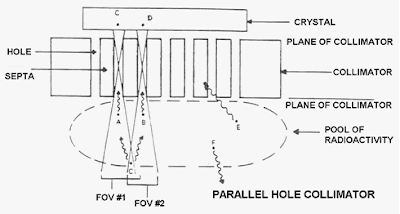
So the problem is this... when the student had placed the patient on the bed, they had unknowingly changed the collimators to high energy collimators instead of the high resolution collimators (VXGP).  While setting up the patient in the computer for the acquisition, the computer had prompted the student that the wrong collimators were installed.  Majority of our acquisition protocols are customized to the organ system that we are scanning (like most modern departments), with a predetermined energy spectrum and energy window, collimation, length of time for the scan etc.. In this case the student did not bother to read the prompt which notified that the wrong collimators were installed for this particular acquisition protocol.  They ignored it and proceeded with the scan.  Thus the 140 keV gamma rays hitting the crystal were limited by the thicker collimation of the high energy collimators, since they were designed for high energy isotopes to minimize the amount of cross talk.  Collimation is one of the fundamental principles of Nuclear Medicine Instrumentation.

Fig. 4  An example of a parallel hole collimator.  With high energy collimators the "holes" are smaller due to the thicker septa and the longer bore, thus limiting the amount of detection or the sensitivity of the collimator.  The reason for this is to limit the amount of cross talk when imaging with high energy isotopes like iodine.  If these modifications were not present, it would increase the amount of scatter and thus decrease the resolution of the image.

Another possible way of getting images to look like those in Fig. 1 and Fig. 2 is by having the wrong energy or energy window settings.  Although a lot of the camera systems all now have presets, but it's always a good habit to check your parameters and never ignore your error messages.

In the end this patient had their total body bone scan, along with their In-111 WBC with sulphur colloid two days later and found no osteomyelitis in the right shoulder.

Friday, 9 March 2012

I-131 Uptake Post Therapy

Fig 1.  Radioactive iodine uptake midline to the body.  The scan was performed 10 days post iodine therapy.

A patient was presented to our department recently with papillary carcinoma.  The right lobe was removed in the early 1990's while the left lobe was removed in 2011. Follow up treatment was provided by administering 7500 MBq of I-131. Ten days after the therapy, a whole body iodine scan was presented with a focal uptake, midline to the body.  By the nature of the location, it's a bit tricky because we want to know if this is focal bowel activity (diverticulum ?) or is it a true lesion (met?).

There are a couple things that we can do to differentiate, or at least provide some clues,  in determining whether the "spot" is  bowel or something else.  They are the following:

1.  SPECT the area of concern to determine where it is within the body and try to correlate this information with any prior or current imaging "work ups".

2.   Acquire laterals, if the SPECT resolution is poor, and compare with correlative imaging.

3.  Have the patient return the department the next day and repeat the image over the midline to see if the "spot" would move.  This would help us to determine if this was bowel activity.

4.  Perform a SPECT/CT of the area to localize the "spot".

Lucky for us we do have a SPECT/CT in the department, and this is what we have acquired.

Fig. 2  Fused coronal image.

Fig. 3 Fused sagittal image.

Fig. 4  Fused transaxial image.

These are the fused images, since stand alone SPECT images of the site does not really provide as much information in comparison to SPECT/CT, because we can't locate where the "spot" is in relation to hard physical anatomy.

Regular biodistribution of iodine includes salivary, nasal-oral, hepatic, bowel and mammary uptake.  Having said that, the radioactive uptake seemed to be quite focal on both the anterior and posterior images, so it was suspicious from the beginning.  Furthermore, if you look closely at figure 1, a "star artifact" (expand the image) can be seen as well.  All in all, the "spot" was suspicious and it revealed a localized metastasis on the lumbar spine. A compression fracture which was also seen on the CT of the area may have contributed to the uptake as well (ie. inflammatory responses) but the patient did not complain of any discomfort.  

Furthermore a follow up biopsy of the spine (L3), confirmed bony involvement.

Friday, 2 March 2012

How Does Attenuation Correction Work?

I think it's one of those questions where you know the answer, but really don't know the answer, because you know the reason why we do attenuation correction (AC), but really don't know how it is applied on our patients.  Thus the question, "how does attenuation correction work?"  

To start, the principles of AC applies to both SPECT/CT and PET/CT alike, even though we are using different isotopes and energy levels for these systems.  

The CT unit is the main equipment piece that helps us to make this work.  The reason why is, it is the x-ray's that shoot through the body, which gets collected by the CT detector array on the other side that provides the AC data.... "but we know that already!".  The problem lies in the fact that the x-rays and the energy of the isotopes are different.  Let's use Tc-99m as an example.  The problem is this, how do you use a 70 keV x-ray to correct for the nuclear medicine SPECT scan if the energy level for acquisition is at 140 keV?  These energies interact and attenuate differently as it traverses through the body!

Fig. 1  At the very top is the CT x-ray tube (rectangle), with x-rays shooting outwards in a fan beam array through the body (ellipse), being received by the detectors arrange in an "U shape" at the bottom.


When the x-rays are produced from the x-ray tube, there are a spectrum of low to high energies generally, where low energy x-rays get absorbed by the tissues whereas the high energy x-rays pass right through the body, if it is used unfiltered. This is something that we do not want because it makes it harder to figure out the AC maps. Thus the x-rays are filtered (wedge or bow tie) to produce an average of 70 keV's to help simplify the process.  The process isn't perfect, but it "hardens" the beam to eliminate the "ends" of the x-ray spectrum.

Fig. 2  The the x-rays are filtered to help simplify the process of AC.

Once we collect the x-ray data from the detectors, the information is reprocessed. The most important piece of information is the linear attenuation coefficient (u), which is calculated by using this formula, aka Beer's Law:

Formula taken from CT1 course, CAMRT

The little (u) can now be used to calculate the CT numbers to differentiate the different densities in the body based on the Hounsfield unit scale on our display monitors.


So the question now is, "How do we put all this information together to understand AC?!?!"

We've acquired our CT and what you see are whole bunch of CT numbers converted to the Hounsfield's scale, based on the (u) values of the CT x-rays.  The next step is to convert this data and create a correction factor for the corresponding voxels in the SPECT scan.  To do this, we need to calculate the new (u) value that is scaled to 140 keV.  Basically, what would be the new (u) value if we converted 70 keV x-ray to 140 keV (the Tc-99m energy that we want to scale it to)?

There's two parts to this scaling:

1.  Formulas to calculate and scale the 70 keV to 140 keV based on the original CT number acquired for your CT scan

2.  A bilinear graph (model) used to convert CT numbers to (u) values for specific radionuclides like Tc-99m, In-111, Ga-67, F-18 etc.

The formulas:

Fig.3  Top:  Formula for (u) for CT values less than 0 (0 being water).  Bottom:  Formula for (u) for CT values greater than 0.  These are bit hard to see, but look them up in this article:  SPECT/CT Physical Principles and Attenuation Correction

The bilinear graph, works hand in hand with the formulas, because it just gives a graphical overview of how the CT numbers are treated when the CT values are below or above CT=0.  The reason for the bilinear graph is to account for the different densities in the body (ie. water and air mix OR water, soft tissue and bone mix).

Fig. 4  Bilinear graph depicting the corresponding (u) values in relation to the original CT numbers based on the CT scan.


Fortunately most of these scaling values have been pre-calculated and installed in the computer in a stored look up table for the reconstruction algorithm... it's been all worked out. To finish it all off, the CT image has to be "dumbed down" to fit the overlying SPECT image, since CT images have higher resolution than nuclear medicine images thus it needs to be reformatted so that it matches the same matrix, slice width and slice position as the SPECT data.  The new scaled AC map is then incorporated into the original radionuclide SPECT projection image, and reconstructed.  The AC map is used to correct the emission counts from the uncorrected SPECT data to provide the final corrected SPECT data.